I first wrote on the Soviet MRR Engineer Company a few years ago at the time I was focused on the task organised groups that the engineers form to support the regiment and did not spend much time trying to unravel the organisational knot caused by disparities in the organisational structure discussed in FM100-2-3 and Isbey's Weapons and Tactics of the Soviet Union. Since then other sources have come to light and in addition a number of new models have been released allowing for better representation of the unit in 1/72 scale. So I thought it would be worth worth revisiting with more focus on the organisation and equipment of the company.

Like all supporting arms the engineer assets available to a combined arms commander include:
- The organic assets associated with the unit or formations
- Attached assets provided by higher commanders dependent on mission and priority. These can be provided for general support or to achieve specific tasks.
Similar to the allocation of artillery assets the need for centralised or decentralised control depends on the specific operation and phasing:
Centralised control is prefered during
- Preparation of an offensive
- Construction of fortifications and minefields
- During river crossings operations
Decentralised control is prefered at the start of the offensive or in going over to the defensive. Engineer planning and advice is delivered by the Chief of Engineer Services at each level of command.

- Create conditions for more effective application of the means of attack,
- Support the unhindered movement of friendly forces in the vicinity of the enemy
- Affect maneuver on the battlefield
- Provide defence for friendly forces from the destructive means of the enemy
- Reconnaissance of the enemy and the terrain
- Preparation and maintenance of routes of movement and maneuver
- Demolitions work and the construction of obstacles
- Fortification and camouflage of positions and areas
- Exploration for sources of water and its supply and purification
- Measures to camouflage troop movements and operations
- Engineer actions to eliminate the effects of nuclear attacks

Engineers are supported in the delivery of these tasks by Motor Rifle and Tank troops as required. Not surprisingly with the Soviet army the organisation and structure of the organisation directly maps to the doctrinal tasks and goals it is set to deliver. At Regimental level that leaves us with an Engineer company as outlined below.

This organisation is derived from a review of a number of sources;
- FM 100-2-3 provides the main components of the structure
- Weapons and tactics of the Soviet Union together with Soviet Combat Engineer Support a research paper by Major J Parr written in 1978 provide the detail of the allocation of equipment to the sections and platoons as well as the view that the technical construction platoon could be replaced by two sapper platoond
- L Graus paper Instant Russian Obstacles, FMSO, 1996 provided the view that the UMZ was deployed at regimental level. Currently I believe the UMZ was deployed in the early 1980s and I have assumed that organisational change was adopted from introduction into service.

The organisational structure shown allows the company to support the standard Soviet Engineer task groupings through which Engineers in the Soviet army delivered support to the Combined Arms Force. Composition of the main groupings are covered in the post MRR & TRR part 3 Engineers. In outline the groupings and tasks are as follows:
- Inzhenernoe Razvedyvatel'nyi Dozor Engineer Reconnaissance Patrol, this may be grouped with other recce units such as Chemical or Regimental or operate independently, they report on the state of roads bridges and obstacles and can work in coordination with or independently of MSDs.

- Otriad Razvevedki i Razgrazhdeniia Reconnaissance/Obstacle Clearing Detachment, these groupings are used primarily to clear obstacles on route to enemy objectives, I assume these are formed by Combat Troops equipped with Mine ploughs and rollers and potentially supported by Sapper platoons
- Otryad Oberspecheniya Dvizheniya Movement Support Detachments, facilitate the maneuver of the first echelon in attack, withdrawal and advance. They will normally operate in front of the main body clearing obstacles and improving routes. They may include security elements from combat or recconnaissance units
- Podvizhnyy Otryad Zagrazhedni Mobile Obstacle Detachments, composed primarily of engineer troops they can be reinforced by other units including mine laying aviation assets. They are configured to rapidly deploy mines, conduct extensive demolitions and deploy and develop obstacles to movement using construction equipment.
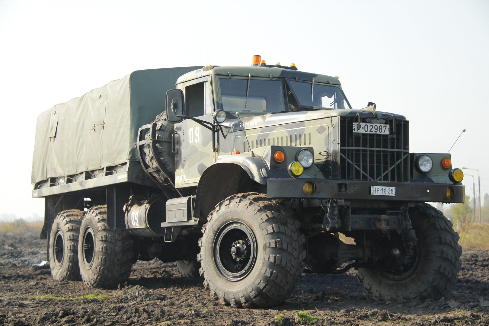
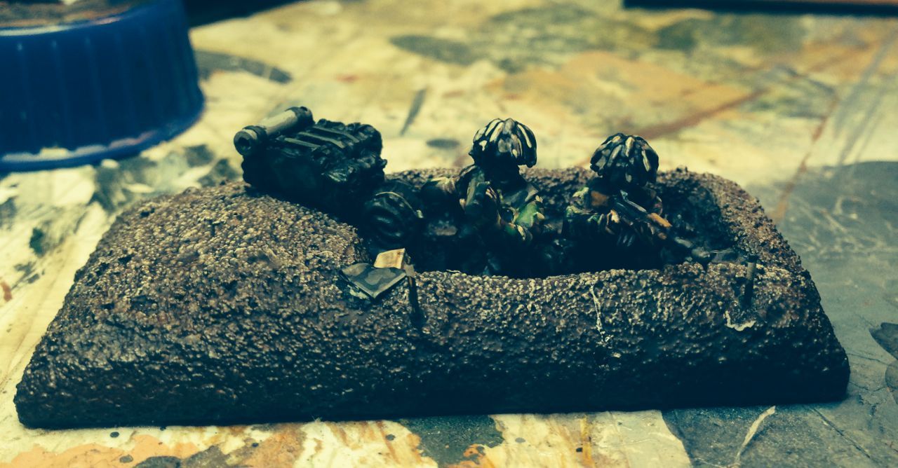
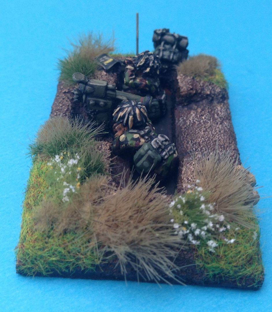
The Company HQ and Services platoon is equipped with 3 Command Vehicles a UAZ 469, BRDM2 and a BTR 60 and a fleet of 8 or 9 trucks for carrying the engineer stores of the regiment, Trucks would either be the 7.5 ton Kraz or the 5 ton Ural and the stores carried were primarily;
- Mine ploughs,
- Mine rollers,
- MTU dozer blades
- Water purification kit.
- Stores for Bridging
I have represented the unit with a BRDM 2 and 3 Kraz Trucks. I decided to use the Kraz trucks primarily to differentiate the engineers from the artillery units in my collection. The Mine rollers and ploughs are represented as separate models which can be attached to any vehicle and the MTU dozer blades I model as permanent attachments to one tank in the tank battalion.
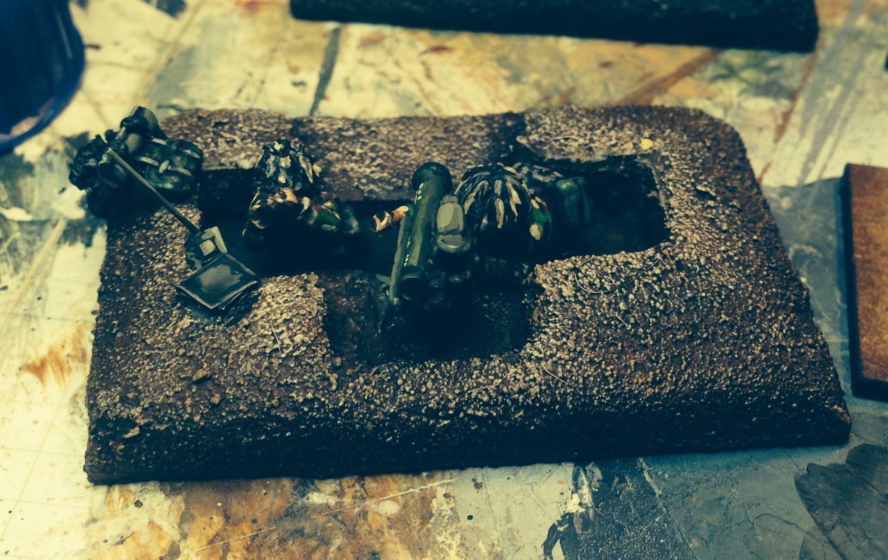
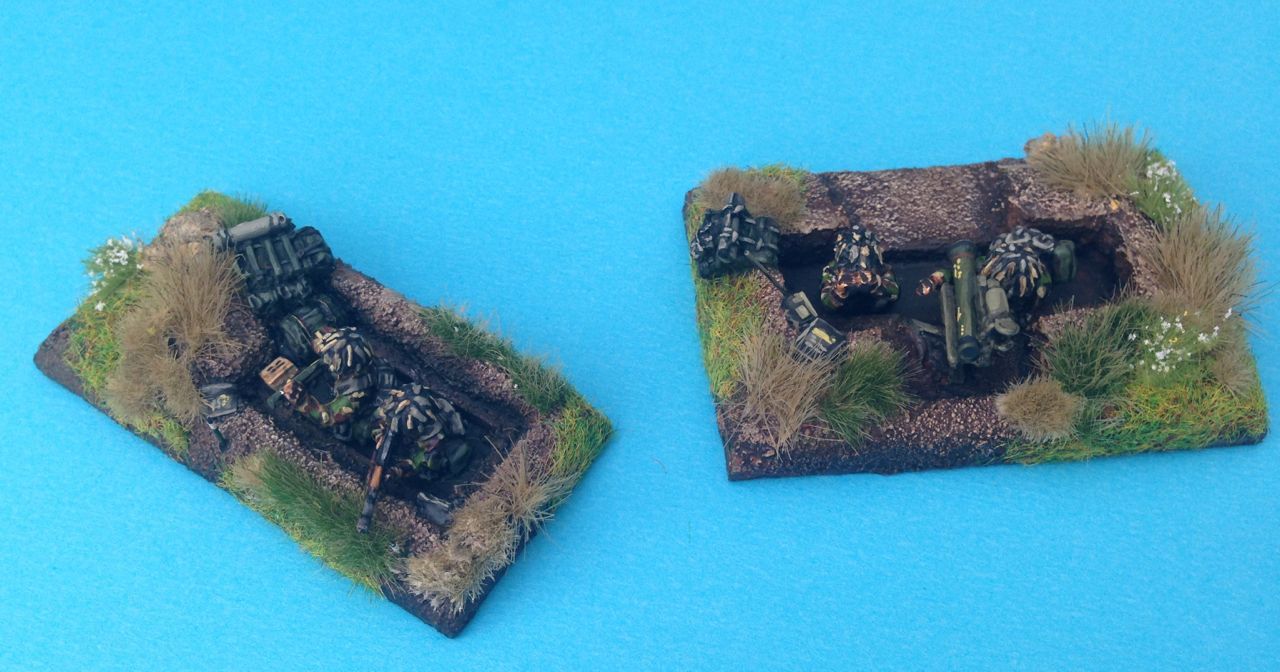
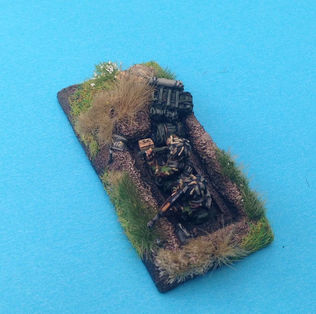
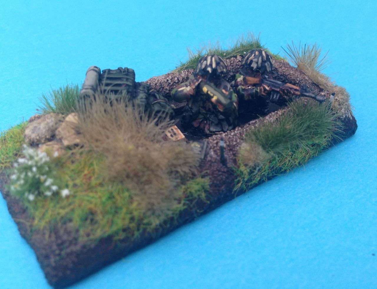
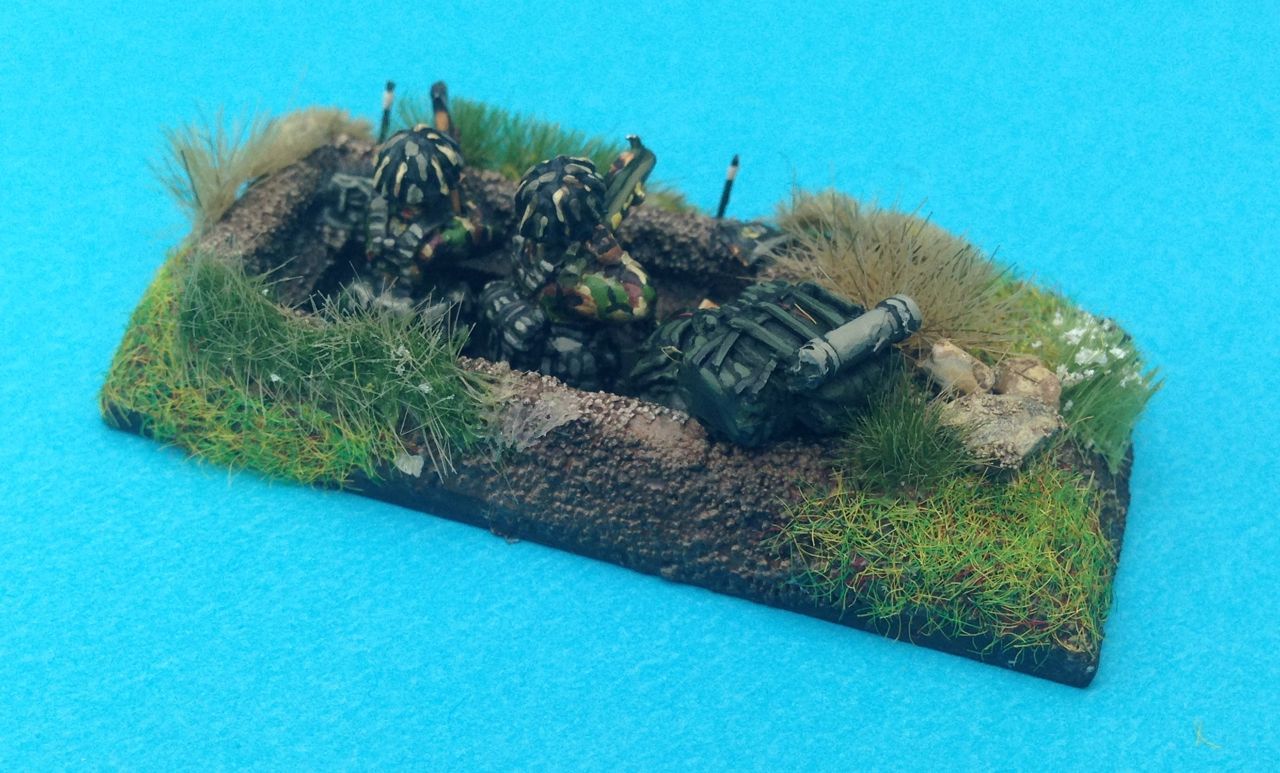
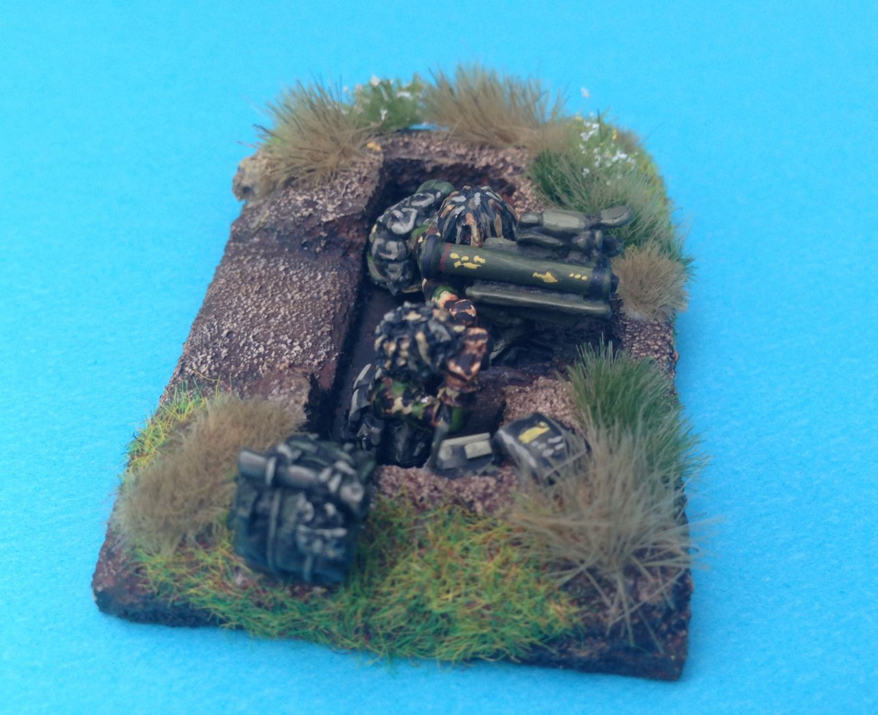
Sapper Platoons
The sapper platoons each consist of 3 sections with each section mounted in a BTR 60 or a truck. Sections are capable of undertaking a variety of tasks including;
- Demolitions and Cratering
- Mine clearance
- General pioneer work.
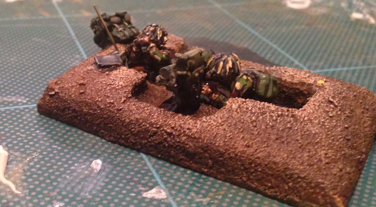
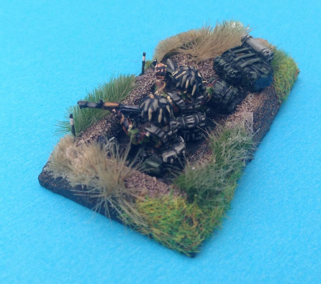
Sapper & Mine Platoon

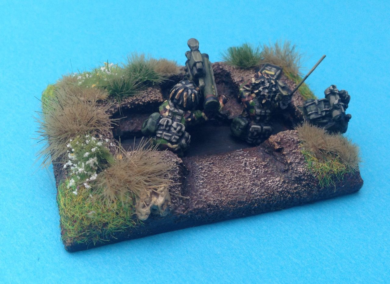
The third Sapper platoon in the company was also the minelaying platoon. Again these could be equipped with APCs or trucks although in this instance the APCs would be BTR 152s as the PMR 3 or PMZ 4 could not be operated from a BTR 60PB due to the rear mounting of the engine. As well as minelaying this platoon could also undertake general pioneer work, demolitions and cratering. I am representing this platoon with 1 BTR 152, 1 PMR3 and a ZIl 131 with a UMZ scatterable mine system as discussed above.

The platoon is equipped with a first line scale of 600 mines, minefields consist of 3 rows and at a 4m spacing this load can deploy an 800m 3 lane minefield in 20 minutes. Reloading takes 10-12 minutes although exchanging the towing vehicles can speed this up. A large minefield would comprise of a number of 200 - 300m blocks with varying orientation and arranged in depth. Blocks could be interspersed with dummy minefields which would just be ploughed. A platoon of 3 Vehicles can lay fairly significant minefields in an hour and smaller ones in 20 minutes.
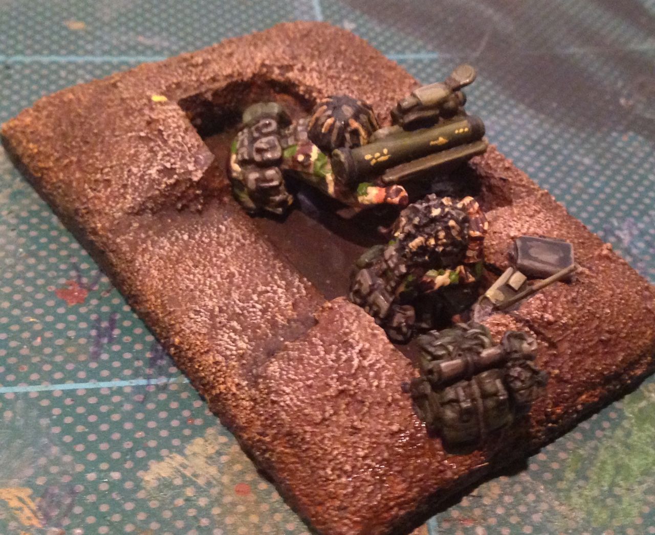
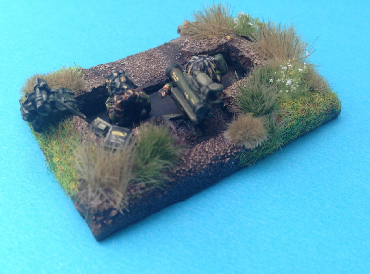
Road & Bridging Platoon
The Road and Bridging platoon comprised of three sections that primarily manned specialist engineer equipment appropriate to the sections primary task, the three sections covered
- Route maintenance and support,
- Bridging
- Obstacle and fortification construction

Road Section

The Road section consists of two vehicles only a DIM mine clearance vehicle and a BAT-M, I am representing it with a single BAT-M.
The BAT-M can be used to develop routes using its forward blade which can be configured in a number of ways depending on the task and the onboard crane. tasks include:
- Grading
- Filling Trenches and Craters
- Clearing rubble and Snow
- Breaching Obstacles
Whilst not primarily designed for digging work it could be deployed to develop fortifications and ditches if required, in this it would be less effective than the purpose built machinery described below. The BAT-M started to be replaced by the BAT 2 at the backend of the Cold War
- BAT-M produced 1953 - 1972
- BAT 2 Late 80s entered service 1988 onward, no significant change incapability

The Bridge section varied between tank and Motor Rifle Regiments, Tank Regiments had 3 AVLBs and a 4 TMM truck launched bridging unit. The MRR had only 1 AVLB and the TMM unit.
The AVLBs that could be deployed included:
- MTU-12. 11m class 50, based on T-54 chassis, production 1955
- MTU-20, 18m class 50, based on T-55 chassis, production
- MT-55, 18m class 50, based on a T-55 chassis, deployed in 3 minutes, production 1969 - 1983
- MTU-72, 18m class 50, based on a T-72 chassis. deployed in 3 minutes, production 1974 - 1992
Regardless of regiment type I am modelling the bridge section as 1 MT-55 and one TMM.
Fortification Section

The Fortification section could be equipped with a few different vehicles in general there was either an MDK-2 or a BTM. the BTM was primarily a trench digging equipment whilst the MDK - 2 could be used to rapidly develop anti tank ditches vehicle scrapes or bunkers. The rest of the section comprised 3 PZM trench excavators.
Digging rates were:
- BTM between 250m - 800m per hour depending on trench depth and soil type. Trenches of 1.1/1.5m depth x 1m width could be produced in straight sections, zig zagging or waves.
- MDK-2 creates a trench 3.5m x 3.5m at around 30m an hour. This seems low compared to the others.
- PZM can dig trenches of upto 3.5 m depth x upto 3.5m width at rates between 35m an hour to 200m an hour depending on soil type and trench size

Game Concepts
Usually engineer tasks other than deployment of AVLBs sit outside the scope of most games. The level of automation deployed by the Soviet Army across all task allow this to be challenged. The obvious candidates are the more rapidly deployed capability options;
- AVLB launched bridge
- Single/duel Span TMM
- Minefield breaching
- Crater filling
- Wire Breaching
- Scatterable minefield deployment
- AT Ditch deployment
- initial trench system creation
- Surface laid minefields
- closure of gaps in obstacles
- initiation of demolitions
Consideration may be given to an opening move of longer duration enabling the placement of obstacles at the commanders discretion or multiple moves of engineering tasks before the arrival of the enemy force or indeed the sequenced arrival of that force over a number of moves all of which would provide scope for in game Engineer play given the rate of production described above and the Soviet doctrine of deployment of obstacles on identified enemy lines of advance. Most of these concepts would need axis of advance or points of entry to be identified to the Soviet commander an activity that could be randomised.


The Soviets doctrine called for the deployment of obstacle belts in front of maneuvering forces in order to achieve surprise and chemical troops smoke units would be deployed to screen the tasks from the advancing enemy forces.
Models
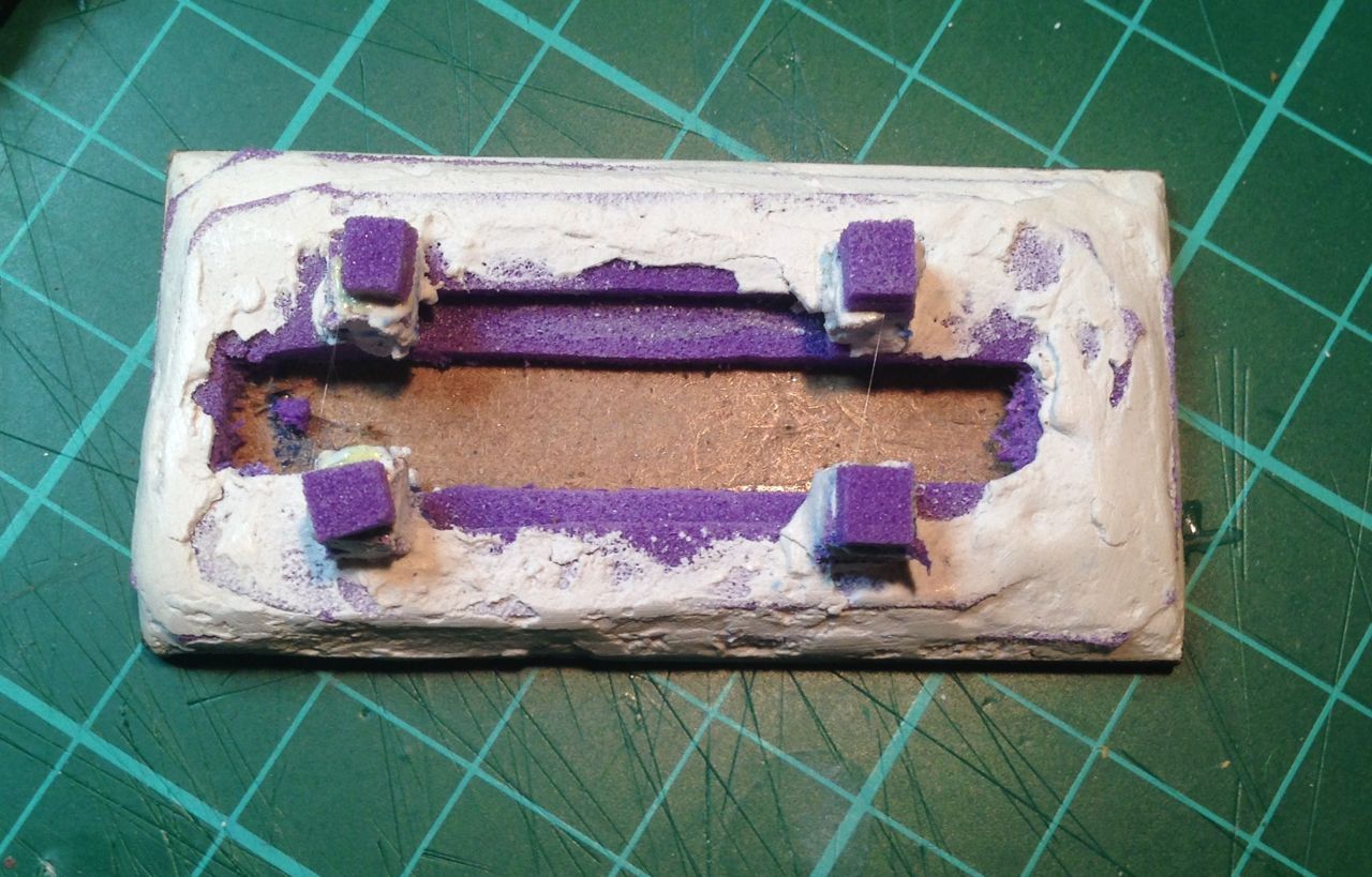
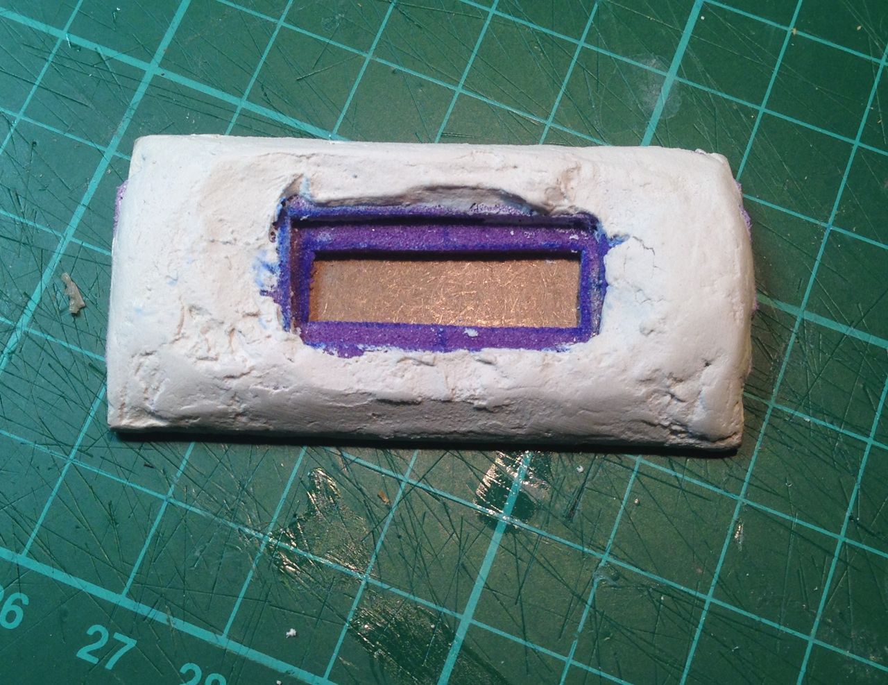
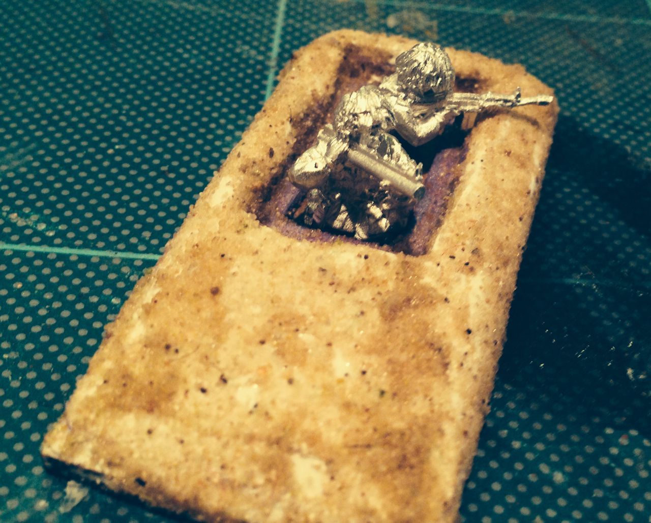
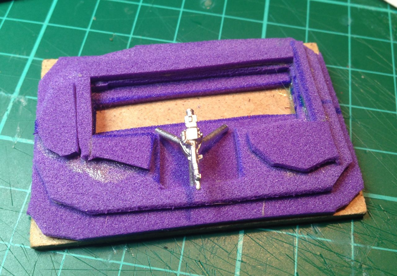
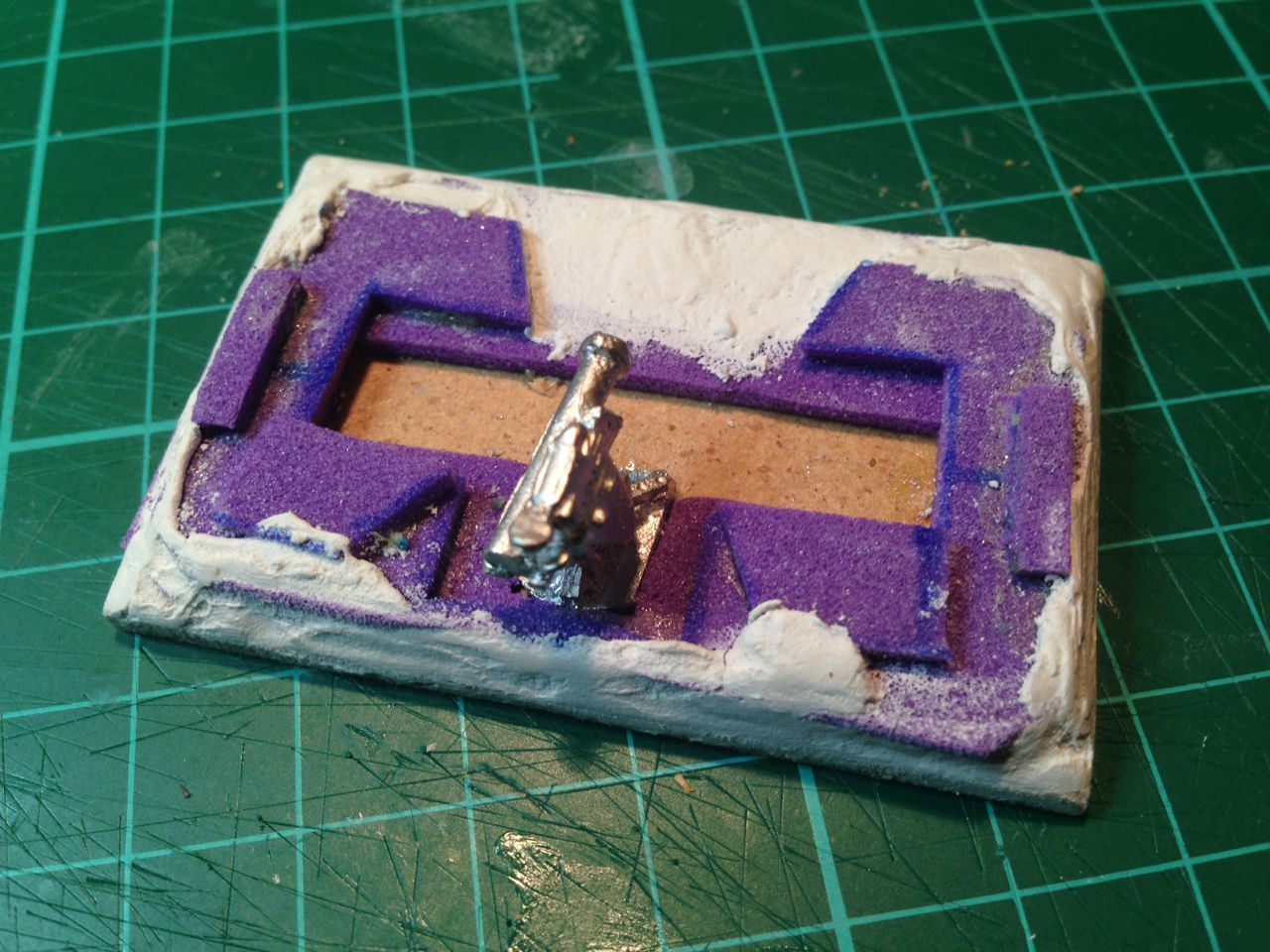
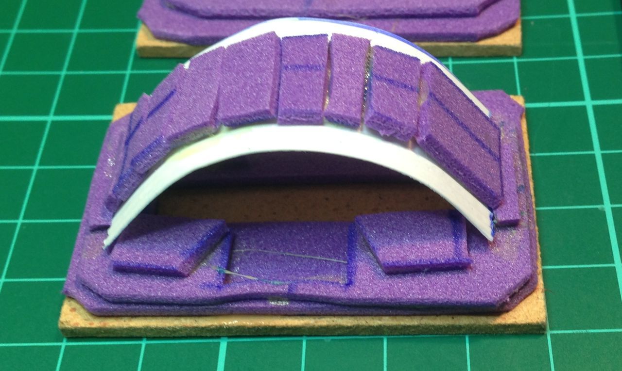
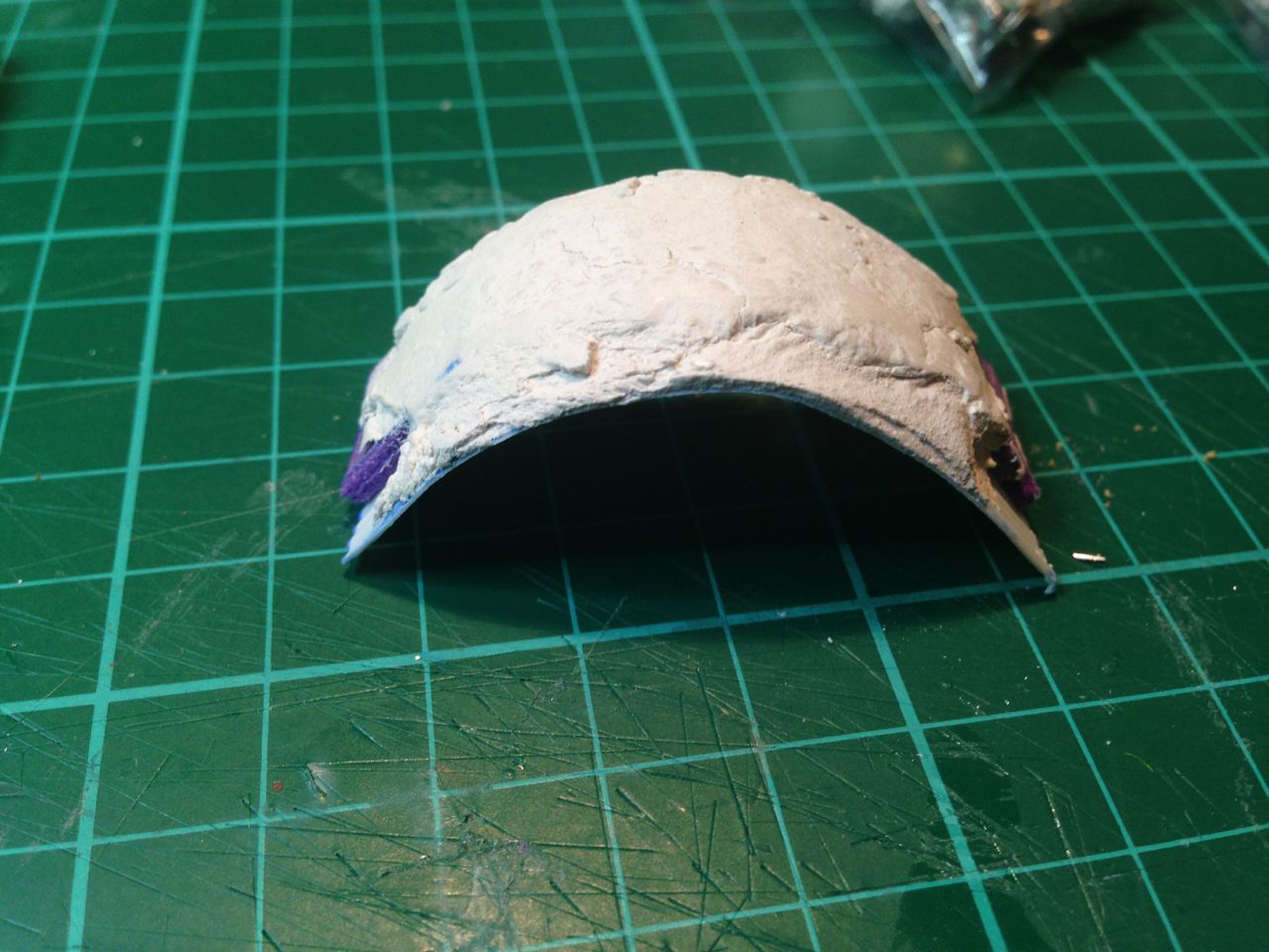
You need of course to build models to represent the engineer assets and for engineering capability that includes both the equipment and the terrain items that indicate that the work has taken place. So creation of engineer units and their employment is a reasonably labour intensive task.
The good news is that over the last couple of years the range of models to support the use of Soviet Engineers in 20mm / 1/72 has increased dramatically and includes figure as well as equipment from such companies as S&S and W Models.
A combination of relatively inexpensive resins and plastic kits will buy you the bulk of the capability with the odd high cost rein from W Models rounding out the capability along with a small amount of scratch building and a little imagination its fairly straight forward to deploy the equipment and figures. A reasonably comprehensive list of models and suppliers for this project is outlined in the table below;

- Deployed equipment bridges
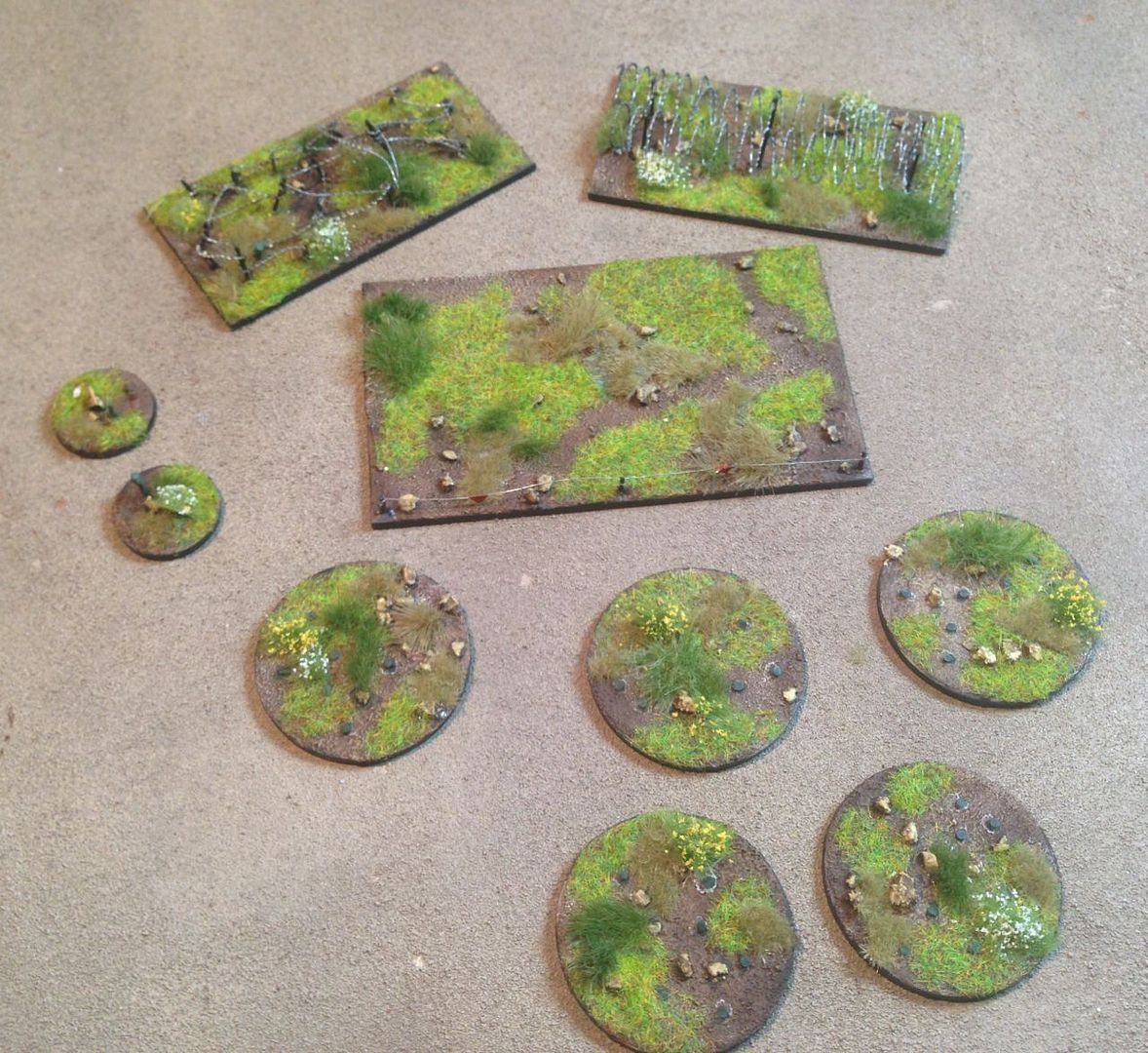
- Minefields, marked and unmarked
- Wire obstacles
- Craters
- AT Ditches
- Trenches
- Trench systems
- Tank scrapes

References:
Web:
BTR 60
Pioneer Battalion 11
Soviet Engineer Digging Equipment
Soviet Combat Engineer Support, US Army Institute for Advanced Soviet and East European Studies
Instant Russian Obstacles, FMSO, 1996
Soviet Engineer Equipment
FM100-2-3
Books:
The Soviet Conduct of Tactical Manoeuvre
Other Posts of Interest:
ORBAT - 1980's Soviet MRR and TRR, Part 3 Engineers
TTP - Soviet Advanced Guard and March Security
Wargames Unit - Soviet MRR, Anti Tank Reserve
Review - Model 1/72, S&S MT-55 Bridgelayer